How to DIY a Drones Jammer
A simple drone Jammer designed to hack unwelcomed civilian drones within your backyard range.
What are Jammers? Commonly Called signal blockers, devices used to block and interfere with radio communication signals
What are Civilian (Commercial) Drones? Also known as unmanned aerial vehicles (UAV), are aircraft without a human pilot on board. The flight is controlled by the remote control of a pilot on the ground. The typical launch and recovery method of an unmanned aircraft is by the function of an automatic system or an external operator on the ground. There are a wide variety of UAV shapes, sizes, configurations, and characteristics.
Why Civilian Drone Jammer? Commercial drones have raised privacy concerns among United States citizens since most of the drones fly equipped with high-quality cameras which can invade people’s privacy, taking photos of people and personal property. Also, drones can be used to smuggle drugs, crash into buildings, act as peeping Toms, drop bombs, shoot guns, and gather personal data on anyone whom drone pilots want to harm. Hence a Jammer to block drone remote control signal to protect our privacy and personal space is required
JAMMER legalization: Jammer which blocks GPS, Cellular communication, and/or WIFI are illegal in the United States, so this Jammer design is for educational purposes only and is not for commercial or personal use.
The Design
What to JAMM? In this design, we will block the most commonly used remote control R/C communication link by commercial drones manufacturer (such as Parrot AR Drones). Common R/C frequencies: Band 1: 2.4 MHz – WIFI g/b/n: ≈ 2.4 – 2.5 GHz Band 2: 433 MHz ISM Band: 433.05-434.79 MHz
Design overview: The design includes two band Jammers (i.e. band 1 & band 2). The RF circuit will consist of voltage controlled oscillator to sweep the required band along with a tuning circuit to drive the VCOs also it will include a linear power amplifier to amplify the output power of the VCO. The tuning circuit will consist mainly of the sawtooth generator to generate the tuning signal along with a noise generator to tune the VCO to the required RF Jamming signal. Last but not least power supply circuit is designed to provide the required DC voltages for the RF and the tuning circuits from alternating 220/110 power input.
RF Power requirements: The maximum power of ISM Bands allowed for a civilian drone is 36 dBm EIRP (Effective Isotropic Radiated Power) with maximum transmitted power of 1 W (30dBm) and the minimum Signal to Noise ratio SNR is 4 dB for data. Hence using simple arithmetic; the radiated power of the RF Jammer must be more than 32 dBm EIRP
To achieve this required radiated power for Band 1 RF circuits, two cascaded power amplifier with a total gain of 30 dB is employed with 3dBm VCO output power and 7dBi Antenna; the radiated power of Band 1 RF circuit is 40dBm which exceeds the required Jamming power required to block “band 1 (2.4 GHz)” civilian drone R/C communications.
For Band 2 (433 MHz) RF Circuit; a high gain power amplifier is utilized with 35dB typical gain and 2 dBi Antenna is employed radiating a total EIRP power of 37 dBm which is more than the required Jamming power required to Jamm “band 2 (433 MHz) civilian drone R/C communications.
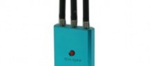
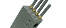
Comparison of Analog Jamming Source and Digital Jamming Source
Full bands Digital drone jammer for MAX 5.5KM rang No.CTSDJ55
Device Parts:
Band 1(2.4 GHz) Jammer RF circuit main parts: The following are the main parts, the rest can be found on the design schematics.
- Linear Power Amplifier: Two RFMD RF2317 linear CATV amplifier

- Voltage Controlled Oscillator (VCO): CRYSTEKCVCO33BE-2400-2500 VCO which covers the frequencies from 2400 to 2500 MHz Voltage tuning input for the VCO is from 0Vdc to 3Vdc, output power of 3 dBm at 3 Vdc and output Impedance of 50 oh which is matched to the input impedance of the power amplifier

- ANTENNA: 7dbi 2.4 GHz Rubber Duck Antenna
Band 2 (433 MHz) Jammer RF Circuit main parts: The following are the main parts, the rest can be found on the design schematics
- Linear Power Amplifier: the Skyworks SKY65116: 390–500 MHz power amplifier. With an internal matching impedance to 50 ohms
- Voltage Controlled Oscillator (VCO): CRYSTEKCVCO33BE-2400-2500 VCO which covers the frequencies from 2400 to 2500 MHz Voltage tuning input for the VCO is from 0Vdc to 3Vdc, the output power of 3 dBm at 3 Vdc and output Impedance of 50 ohms which is matched to the input impedance of the power amplifier
- ANTENNA: 1/4 WAVE WHIP, SMA- right angle, 433MHZ
Tuning Circuits main parts: The following are the main parts, the rest can be found on the design schematics.
- 555 Timer: To generate square want which will be converted to triangular wave to tune the VCO
- Zener Diode with power amp: to generate a white noise signal
Power Supply Parts: Power supply parts are shown on the design schematic.
References: – GSM-900 Mobile Jammer CTSTechnologys.com